EtherNet/IP (Ethernet/Industrial Protocol) is a communication system suitable for use in industrial environments. EtherNet/IP allows industrial devices to exchange time-critical application information. These devices include simple I/O devices such as sensors/actuators, as well as complex control devices such as robots, programmable logic controllers (PLCs), welders, and process controllers.
EtherNet/IP uses CIP (Control and Information Protocol), the common network, transport and application layers also shared by ControlNet and DeviceNet. EtherNet/IP then makes use of standard Ethernet and TCP/IP technology to transport CIP communications packets. The result is a common, open application layer on top of open and highly popular Ethernet and TCP/IP protocols.
EtherNet/IP provides a producer/consumer model for the exchange of time-critical control data. The producer/consumer model allows the exchange of application information between a sending device (e.g., the producer) and many receiving devices (e.g., the consumers) without the need to send the data multiple times to multiple destinations. For EtherNet/IP, this is accomplished by making use of the CIP network and transport layers along with IP Multicast technology. Many EtherNet/IP devices can receive the same produced piece of application information from a single producing device.
EtherNet/IP makes use of standard IEEE 802.3 technology; there are no non-standard additions that attempt to improve determinism. Rather, EtherNet/IP recommends the use of commercial switch technology, with 100 Mbps bandwidth and full-duplex operation, to provide for more deterministic performance.
Notes 1.When configured, IRT Analyzer behaves as an EtherNet/IP adapter or server. It does not establish communication with other devices by itself, but only reacts to transmissions originated by other modules (called clients). A client device is needed to receive and interpret data produced by IRT Analyzer. 2.IRT Analyzer EtherNet/IP server starts when DAQ Configuration dialog is opened or when the automation mode is started or being configured. Otherwise, the server is not running and is not visible for other devices in the network. Once the server is started it continues to run as long as IRT Analyzer is running. |
Configuring EtherNet/IP server
EtherNet/IP adapter in IRT Analyzer is implemented as a DAQ module and can be enabled in 'DAQ Configuration' dialog (main menu 'Automation | DAQ Configuration').
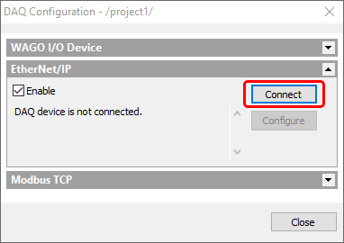
Firstly, it is necessary to specify which Ethernet adapter (PC may have several Ethernet adapters) is to be used by the EtherNet/IP server. Press 'Connect' button to select an adapter. When Ethernet adapter is selected you will see a message confirming this: "Connected to 192.168.1.33 - Local Area Connection".
After that you need to define how much data is needed to fit all inputs and outputs used in the automation project. Press 'Configure' button.
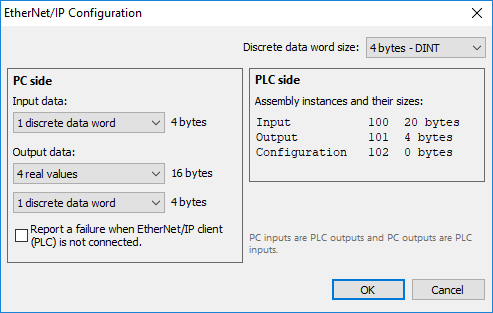
We can look at the data from the two sides - PC and PLC (EtherNet/IP network).
PC (IRT Analyzer) side
On the PC side we define how much data is needed as input data and how much as output data.
· Input data: we can use each bit of the input data as a discrete input for DAQ conditions.
·Output data: consists of real data (4-byte floating point numbers) used as outputs for measurements and discrete data used as outputs for alarms and signals.
For convenience purposes and for compatibility with Rockwell software discrete data is divided into words which can have different length - 8 bit per word (1 byte, SINT), 16 bit per word (2 bytes, INT) and 32 bit per word (4 bytes, DINT).
PLC (network) side
To be used by EtherNet/IP client's data is packed into Input and Output assemblies (objects defined by CIP protocol).
Note Please note that from the network point of view (PLC side) data directions reverse. IRT Analyzer input data is output data for PLC/network and IRT Analyzer output data is input data for PLC/network. |
Input assembly
·Instance number 100
·IRT Analyzer outputs go here
·First real values, then discrete values
RData: array of 4-byte real values (measurement outputs) |
DData: array of discrete data words (outputs from alarms and signals) |
Output assembly
·Instance number 101
·IRT Analyzer reads inputs from here
·Only discrete values are supported
DData: array of discrete data words (inputs for DAQ conditions) |
Configuration assembly
·Instance number 102
·There are no configuration variables used, so the size of Configuration assembly is always 0.
'Report a failure when Ethernet/IP client (PLC) is not connected' option
When IRT Analyzer depends on external signals, it is important to properly handle situations when there is nobody connected and data is not sent (PLC is not connected).
Event |
Option is enabled |
Option is disabled |
PLC is not connected when automation mode starts. |
All processing is suspended until PLC is connected, a wait dialog is shown. |
Automation mode starts immediately, input values are undefined. |
PLC disconnects when automation is running. |
The system goes to the failure state, input values are undefined. |
No system failure, input values keep their last set states. |
Selecting measurements and alarms/signals to fill Output data
Data for EtherNet/IP is not filled automatically. You need to manually select measurements and alarms/signals that will be written to the data array before it is sent to EtherNet/IP clients.
Use 'Measurement Outputs' tab in the 'Automation Mode' dialog to fill the RData (real data) array:
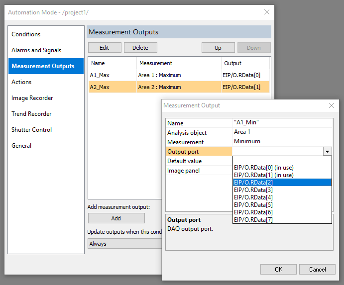
For details, please read "Measurement outputs" topic.
Use 'Alarms and Signals' tab in the 'Automation Mode' dialog to fill the DData (discrete data) array:
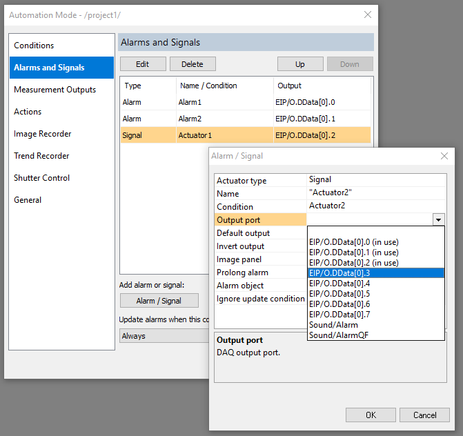
For details, please read "Alarms and signals" topic.
Using Input data in discrete inputs
Use 'Conditions' tab in the 'Automation Mode' dialog to test bits in the DData (discrete data) array:
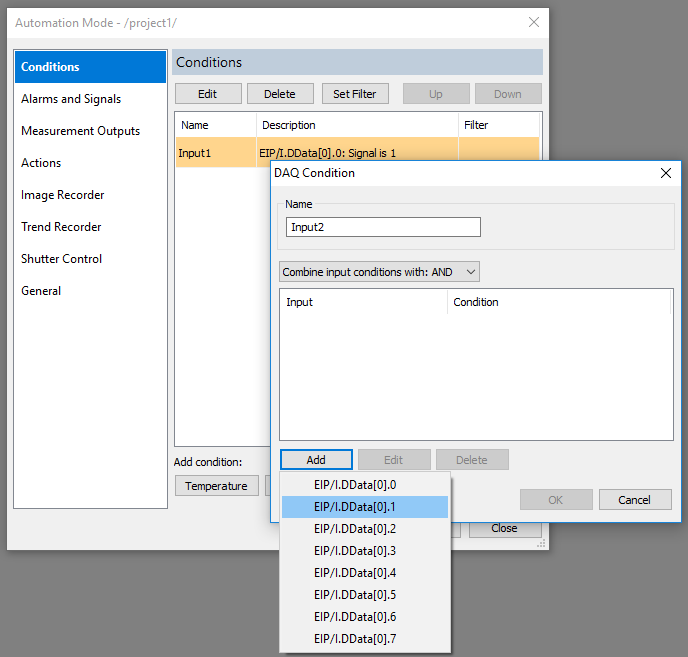
For details, please read "DAQ Conditions" topic.