When IRT Analyzer EtherNet/IP DAQ module is enabled and running, you can connect and exchange data using any EtherNet/IP client (scanner) device or software. We will discuss here how to program an EtherNet/IP enabled PLC in Rockwell Studio 5000.
Start Rockwell Studio 5000 Logix Designer, create a new project for your PLC and follow the steps below.
Import the EDS file
EDS files contain information needed for Studio 5000 software to communicate with EtherNet/IP enabled devices. IRT Analyzer EDS file is delivered with IRT Analyzer installation and must be imported in Studio 5000.
EDS file is in the program installation folder (usually "Program Files\GRAYESS\IRT Analyzer 7").
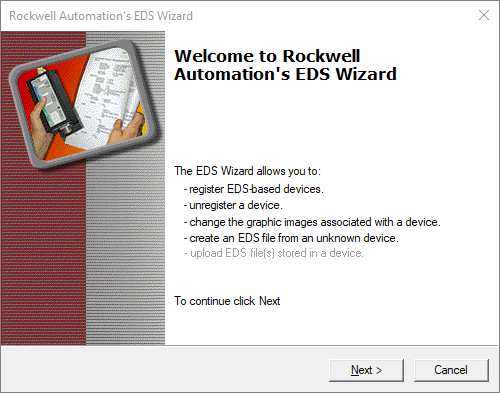
In the main menu of Logix Designer select 'Tools | EDS Hardware Installation Tool' and follow the instructions on the screen. This step should be done only once, no need to do it for every new project.
Create I/O module for IRT Analyzer
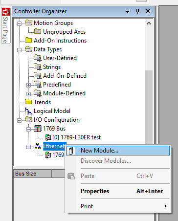
In 'Controller Organizer' window, in the tree find 'Ethernet' item, right click on it and select 'New Module'.
You will see a dialog with a list of all supported modules. In this list find an entry with Catalog Number 'THERMOVIEW-EIP', click on it, then click on 'Create' button. This will bring the 'New Module' dialog:
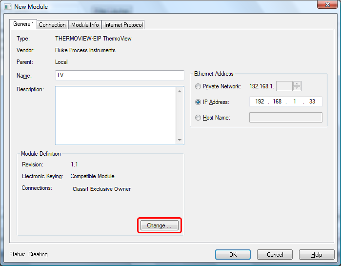
Type a name for the module, set the IP address and then press 'Change' button to open 'Module Definition' dialog and to configure the connection type and data sizes.
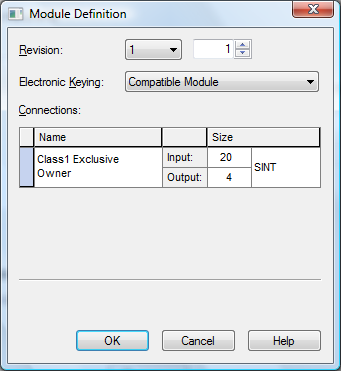
It is important to correctly define Input and Output assembly sizes to match them with sizes set in IRT Analyzer EtherNet/IP DAQ module configuration.
Sizes are defined in words of the following types:
·SINT - 1 byte
·INT - 2 bytes
·DINT - 3 bytes
·REAL - 4 bytes
For example, if you set the size to be 10 INT, size in bytes will be 10 x 2 = 20 bytes.
1.Logix Designer can only treat data as an array with elements of one type. If your Input assembly contains both REAL and discrete data you should select any type here and then convert data to a user-defined type in the PLC program before you use it. 2.It is not possible to define different types for Input and Output data. |
Connection types
There are three types of connections available:
1.Class1 Exclusive Owner: this type is used in most cased. PLC will establish an exclusive connection, will read the Input data from IRT Analyzer, and will update the Output data. Only one device is allowed to control the outputs and therefore only one connection of this type can be active simultaneously.
2.Class1 Input Only: a non-exclusive connection will be established allowing PLC to read the Input data. No access to the Output data.
3.Class1 Listen Only: this connection type is like Input Only (allows reading the Input data) with the difference that it works only when another device is connected using the Exclusive Owner connection type and multicast data transmission. Listen Only connection is stopped automatically when the exclusive owner device breaks its connection.
"Class1" means that IRT Analyzer EtherNet/IP server behaves according to Transport Class 1 specification defined by Common Industrial Protocol.
Packets production frequency
On the 'New Module' dialog select 'Connection' tab.
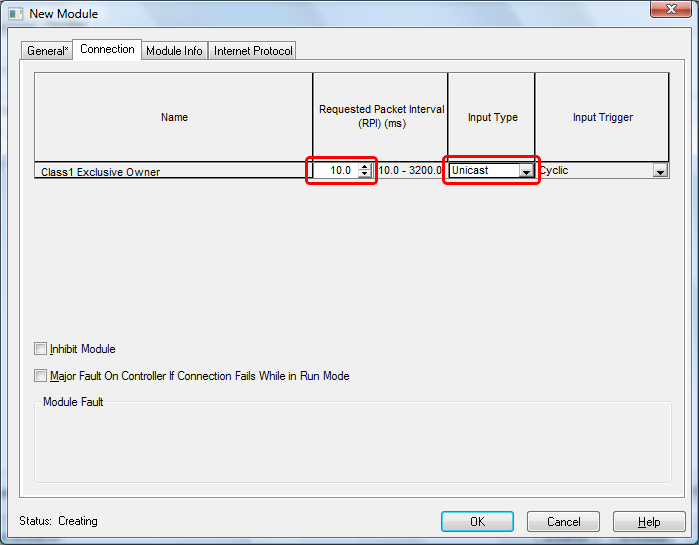
To define packet production frequency, set Requested Packet Interval (RPI) in milliseconds. Also at this page it is possible to select unicast or multicast transmission types.
Supported production trigger type is only Cyclic. Change-Of-State and Application types are not supported.
There is nothing more that you can configure in 'New Module' dialog. Press 'OK' to close the dialog and to create IRT Analyzer module in Logix Designer.
Check that PLC can connect to IRT Analyzer
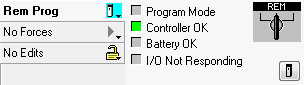
If you will go online with the project now, PLC will try to connect to IRT Analyzer and will show connection status. When everything is fine, you will see green I/O status indicator:
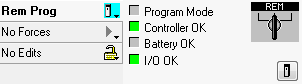
If something is wrong, you will see I/O indicator blinking:
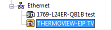
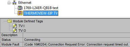
You can find out what problem occurred in the module status window (IRT Analyzer module must be selected in the tree):
To see data values, use 'Controller Tags' window (can be found in the 'Controller Organizer' tree):
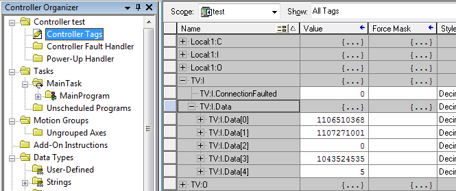
As you can see on the screen shot, using controller tags generated automatically by Logix Designer is not convenient because all data is displayed as an array of elements of one type, while data may contain real and discrete values. To overcome this limitation, you can convert data into a user-defined type that better suits your needs.
Create user-defined data types
Create two user defined data types called TV_Inputs, and TV_Outputs. To do this, in the 'Controller Organizer' tree right click on ‘User Defined’ and select ‘New Data Type’.
TV_Inputs
Define TV_Inputs type as shown on the screenshot:
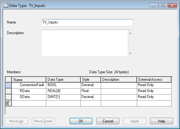
Please note:
1.It is important to create ConnectionFault field. It is not part of data sent by IRT Analyzer, but it is present because of EtherNet/IP protocol.
2.Sizes of RData and DData arrays must correspond to the full size of the Input assembly.
3.Instead of RData array you can use a list of variables that corresponds to the specific measurements selected in IRT Analyzer.
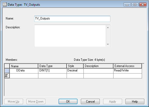
TV_Outputs
Create TV_Output type in the similar way:
Next step is to create controller tags with the new types. Open the controller tags and click on the ‘Edit’ tab. Add two tags TV_IN with data type TV_Inputs and TV_OUT with data type TV_Outputs:
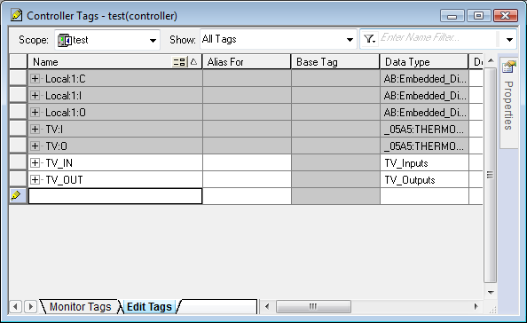
Now new tags are present, but they are not filled with values. We need to write a small PLC program to fill them with real data.
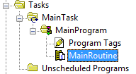
In 'Controller Organizer' window double-click on ‘MainRoutine’ to enter the ladder logic program.
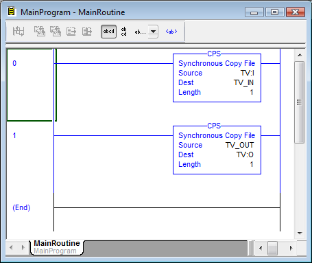
Insert ‘Synchronous Copy File’ (CPS) instructions to copy the auto-generated tags to the user-defined tags (TV:I to TV_IN and TV_OUT to TV:O). Please note the copy directions, they are different for input and output data.
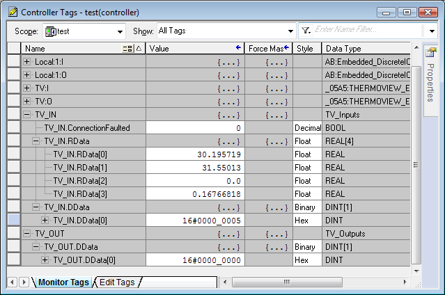
Download the project to the controller and set the controller to the RUN mode. Now 'Controller Tags' window shows the data in a better way: